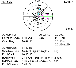
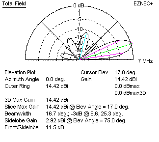
At first glance our response might be this is a lot of gain. After all, the gain is a whopping 14.42 dBi for this 414 foot long 290 foot wide rhombic antenna. But to get a good idea of the real gain, we should compare it to a dipole or some other standard antenna at the same height. When we do that, we find this large 40 meter rhombic antenna has about (14.42 dBi - 8.5 dBi) 6 dBd gain. The efficiency is a fairly low 46.6%
Let's double the size and readjust side angles for optimum gain at the new leg length and see what happens......
We now find the following design specifications for an even larger 4 wavelength-per-leg 40 meter rhombic:
V angle at each end: 47 degrees
Side length: 504.4 feet
Overall width: 687.9 feet
Overall length: 737.9 feet
This antenna would use over 2000 feet of wire, and here is how this monster antenna performs at a height of 200 feet above ground.
From EZnec+ ver. 5.0 we have the following patterns:
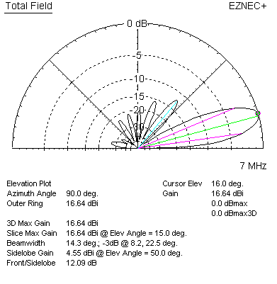
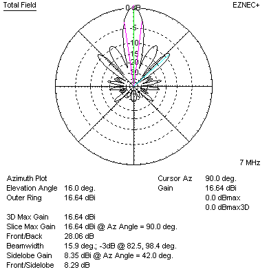
The overall efficiency is 47.2%
This rhombic has 16.64-8.5 = 8.14 dBd gain. This is actually about the gain of a pair of 3-element Yagi antennas stacked. Let's compare the Rhombic to a pair of three element Yagi antenna for 40 meters. Here is the pattern and gain of my two-antenna high 40 meter stack of three element Yagi antennas:
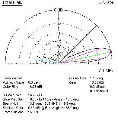
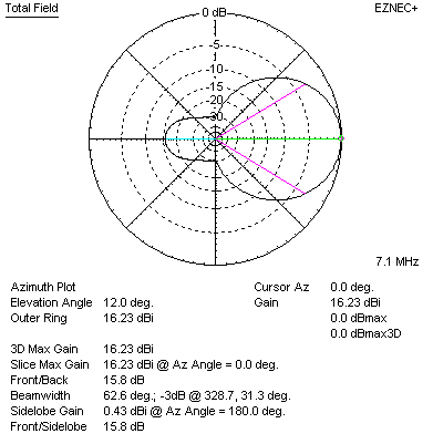
The gain of this antenna system is 7.73 dBd. My two three-element 40 meter antennas are within 1/2 dB of a rhombic 200 feet high occupying a 700 ft by 750 ft area. More important when we look at patterns, the 40 meter Yagi antennas have a cleaner broader pattern. This means less fading and better coverage in the target area using the much smaller Yagi antenna system!
Let's try comparing the rhombic to my planned distributed feed curtain array:


My planned curtain, at 285 feet high and 340 feet wide, has 21.9 dBi gain. Referencing a dipole over earth this is 21.9 - 8.5 = 13.4 dBd gain.
40-meter Rhombic Performance Comparison
| Antenna | Physical size W x L x H | -3dB Beamwidth | Typical gain over dipole | Typical ERP with 1500 watts applied |
Antenna Efficiency |
| PA6Z rhombic 2-wave per leg | Not given | ? | 2.3 dBd | 2,500 watts | ? |
| optimum 2-ave per leg rhombic at 120 feet | 290 x 414 x 120 feet | 23.3 degrees | 6 dBd | 6,000 watts | 46.6% |
| stacked 3 el. Yagi 40m Antenna at W8JI | 70 x 50 feet x 180 feet | 63 degrees | 7.7 dBd | 8,500 watts | 98% |
| optimum 4 wave rhombic at 200 feet | 690 x 740 feet x 200 feet | 16.3 degrees | 8.6 dBd | 11,000 watts | 47.2% |
| Curtain at W8JI | 340 x 35 feet x 280 feet | 19.3 degrees | 13.4 dB | 33,000 watts | 98% |
NOTE: Leg length is the length on each side of the four sides of the elongated rhombus or diamond.
Inverted V antenna
In the 1970's I actually had a true inverted V antenna on an FM broadcast tower in a swampy area with wet rich black loam soil. The apex of the antenna was around 400 feet high with legs going up and coming down several hundred feet long.
The inverted V antenna or vertically polarized half-rhombic is half of a standard rhombic turned on its side. Theoretically the terminated inverted V antenna uses the ground below the antenna to make up the "missing half" of the rhombic.
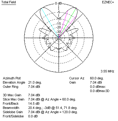
Here is a model of an optimized inverted V half-rhombic over perfect soil:
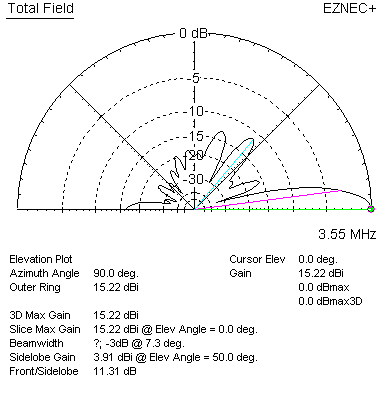
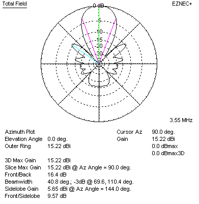
This antenna is terminated with a 400 ohm resistor, and is worked against 25 radials 1/4 wavelength long. It also has a single wire connecting the grounds below the antenna. Gain of the inverted V over perfect earth is 15.22 dBi, or about 6.7 dB over a dipole at optimum height.
Changing the above antenna's earth to good soil (15 ms/m) with no other changes we have the following patterns:
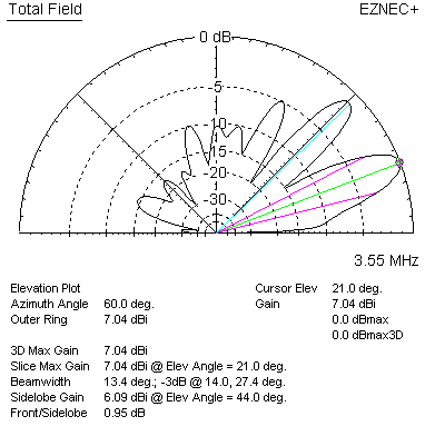
Gain is now 7.04 dBi, or -1.5 dBd. The antenna has a slight loss from a dipole at optimum height.
This is with no conductor or antenna changes. The only change is the soil type, which went from perfect lossless soil to good soil.
This actually agrees with my tests at the broadcast station. While I could get reasonable F/B ratio, I had loss over a dipole in the direction the antenna was pointed. After one season I removed my large inverted V antennas and went with a regular dipole antenna about 330 feet in the air.
V-Beam Antenna
The V-beam antenna is the first part of a rhombic antenna. It omits the closing end of the rhombic. As such, we can model it by removing the outer half of a rhombic. This is a four wavelength-per-leg 40-meter V-beam antenna:
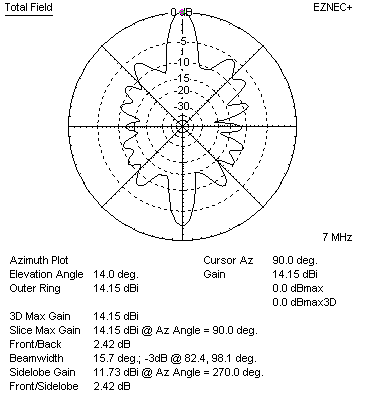
Gain is 14.15 dBi, or about 6 dB over a dipole. This gain is approximately equal to a small three element Yagi antenna. The main problems is, like the rhombic, the half-power beamwidth is very narrow for the gain. A low gain-beamwidth product occurs because antenna efficiency, even for unterminated systems, is only around 70%.
Much of the 30% power loss is in earth below the antenna. Efficiency climbs to 92% when this antenna is over perfect earth. In the case of perfect earth, the remaining 8% loss is due to copper losses in the very long #8 copper antenna conductors.
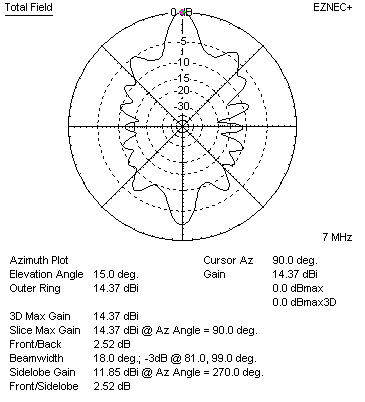
Unfortunately lossless earth doesn't significantly extend the main lobe. Lossless earth primarily fills the nulls, and widens the main lobe. This is a good thing from the standpoint that signals not directly in the main axis improve at no penalty to signals along the main axis.
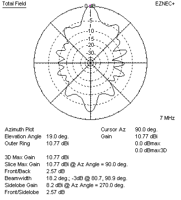
Long wire arrays are also height sensitive. Reduced height greatly lowers efficiency, and a good goal for minimum height is 1/4 of the antenna's leg length. The 4-wavelength per leg V-beam had 6 dBd gain when just under 1 wavelength high.
Reducing height to just under 1/2 wave reduces gain to about 3 dBd or less. The antenna gave up almost 4 dB of antenna gain for a 60-foot height change on a 40-meter antenna, moving it into the gain range of a simple small extended double Zepp wire antenna. The extended double Zepp would have a wider main lobe for the same gain, because it has higher efficiency. It would also have deeper nulls in the null area.
Conclusion
Rhombic and related V antennas are often described as extremely high gain antennas, but that claim seems to be a little exaggerated or inflated. A 2-wavelength per leg rhombic actually has about the same gain as a single three-element monoband Yagi antenna on the design band. Most of the rhombic's performance limitations come from the high levels of spurious lobes and the very poor efficiency, especially over normal soil. The rhombic has one of the poorest gain-per-acre rankings of any high gain HF antenna array. On the other hand a rhombic antenna does have the very distinct advantage of working over very wide frequency ranges with good SWR and gain, something a basic monoband Yagi can never do. The rhombic is also a simple antenna, requiring only four supports (three supports for the V beam, and one support for inverted V derivatives).
In a large properly designed rhombic, slightly less than half of applied RF power is lost in the termination system. That power is converted to heat. Right away this puts the rhombic at a ~3 dB disadvantage to other more efficient antennas with a similar overall pattern shape or half-power beamwidth. There are ways to use this power but generally very little appears in rhombic resources.
Efficiency and gain could be improved if we recirculated termination power. Rather than converting the power to heat, we could recombine the termination RF back into the main feeder system. Such recombining or recirculating schemes would be fairly simple, although they would require readjustment if the operating frequency was changed. A recirculating system would be comprised of an impedance matching network or stub and phasing system to bring the termination signal back in phase with the applied power. By recombining power that would otherwise be wasted as heat back into the feed system, system gain would increase 2 to 3 dB. ( I actually used such a system with an "inverted V antenna", which is actually a vertically polarized half-rhombic antenna. )
Even though not quite the extremely high gain system we are led to believe, the rhombic is not without major advantages over other antennas. It is easy to construct and somewhat non-critical of dimensions. It offers very wide bandwidth performance, being competitive with large log periodic arrays. If we need an easy-to-install very broadband antenna that can easily handle high power and if we are not particularly worried about gain or efficiency, a rhombic is a worthwhile antenna to consider. The many spurious lobes, while they do rob significant power from the main lobe, can also fill in other directions while transmitting. This is sometimes a plus for broadcasting, if we can align the side lobes with populated areas. Rhombics are not the extremely high gain antennas we are sometimes led to believe, but they do have very distinct advantages when it comes to bandwidth, power handling, ease of construction, and physical and electrical simplicity. The rhombic is a moderate gain very wide bandwidth antenna capable of handling very high power.
Since 11/11/2008
